Introduction
In this example we will simulate the below setup with a gateway connected to two remote Modbus units via a network of RF-COM units
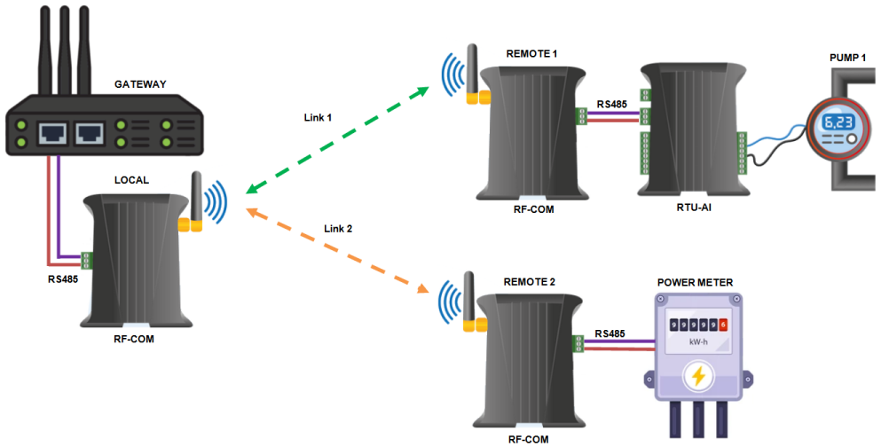
In this setup the Gateway unit uses the local RF-COM unit to create RF links to either remote branch, once the link is created Modbus requests can then be sent to either the remote RTU-AI or Power Meter devices to obtain data point values.
The RF-COM units act transparently so once the respective link has been setup the Modbus application running on the Gateway sends requests through to the remote device just as same as if device was directly attached to it's serial port.
Only one set of local and remote RF-COM units can be linked together at a time.
Worked Example
In this example to simulate the Power Meter and RTU-AI+Pump Sensor setup we will use a Windows PC running two instances of a Modbus slave simulator, we will assign each of these to a separate serial port with an RF-COM unit attached.
For this setup you will need the below parts to create the additional serial ports and RS485 interfaces needed
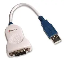
2x FTDI USB to RS232 adapters : https://uk.farnell.com/ftdi/chipi/cable/dp/2352019
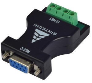
2 x RS232 to RS485 Adadapters : https://www.ebay.co.uk/itm/363059105715
Hardware Setup
The hardware configuration for the setup is shown below
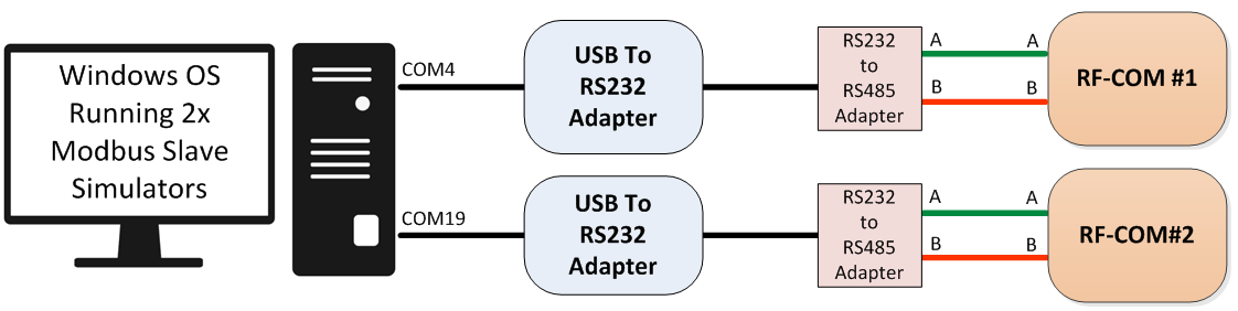
Note that once the FTDI USB RS232 device have been plugged into the Windows PC they will automatically install the necessary software drivers and create two additional virtual serial ports, with new associated COMx numbers, in our example the adapters created COM4 and COM19 serial port interfaces.
Software Installation
Next Install Windows Modbus Slave Simulator, this simulates a generic Modbus device and allows you to enter values stored in different registers.
https://sourceforge.net/projects/modrssim2
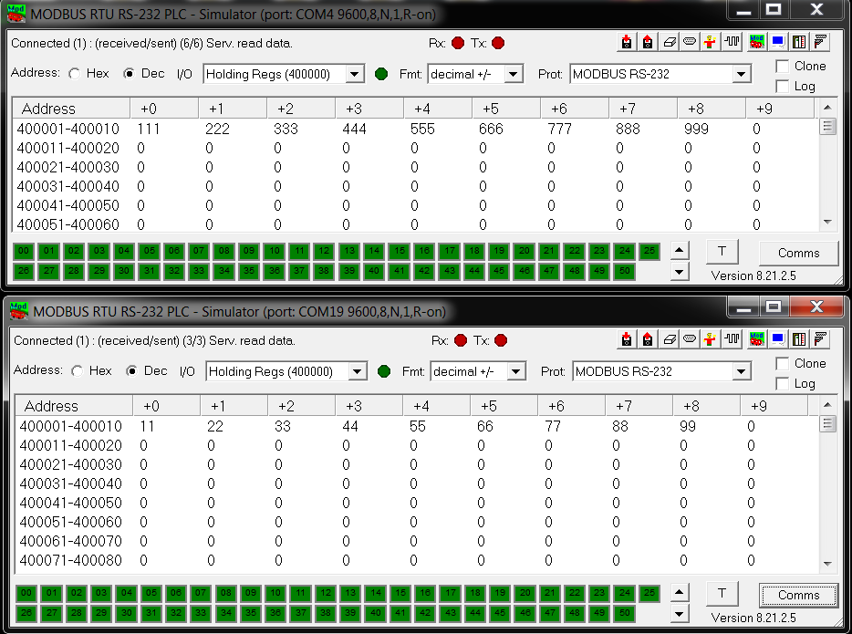
Configure two instances of the Modbus Slave Simulators, with each setup to be running attached to a different virtual COM port (created by the USB to RS232 adapter) and sample values entered as below. Use the 'D9' icon and the 'Plug' icon to control both serial port and connected/disconnected settings.
In our case one simulator is connected to COM4 and the other to COM19 (9600 8N1 are the default baud rate settings), we have entered a different set of sample values on each simulator as this helps to illustrate the results are being obtained from different controllers.
The next step is to install software utilities on the gateway unit for configuring and controlling the RF-COM network. Following the installation steps on the download page lined to below to install both the support library and main python apps.
https://github.com/synapsertu/rf-com
# Install support library
apt-get update && apt-get install python-serial python-setuptools
mkdir pythonxbee
cd pythonxbee
wget https://github.com/synapsertu/python-xbee/archive/master.zip
unzip master.zip && cd python-xbee-master && python setup.py install
cd ../..

# Install main RF-COM apps
mkdir xbeecom
cd xbeecom
wget https://github.com/synapsertu/rf-com/archive/main.zip
unzip main.zip && cd rf-com-main
chmod +x *.py
Initial RF-COM Setup
Next on the Gateway unit and run the command sequence as shown below, this process configures the local RF com unit attached to the gateway and also runs the initial network discovery process.
These steps only need running once as once the network setup and discovery process has been run the tool will generate a configuration file the other tools can then use.
Note that you must be in the folder you installed the rf-com main apps to (e.g. xbeecom/rf-com-main) in order to run these utilities as they are not been copied to the /usr/local/bin folder.
In our setup the local RF-COM unit was connected to the Gateway via a USB interface cable, so the port used was ttyUSB1, you will need to alter this depending on your own setup.
./setlocalxbeemode.py -p ttyUSB1 -b="9600,8,N,1" –a
./configurenetwork.py -p ttyUSB1 -b="9600,8,N,1"
./setlocalxbeemode.py -p ttyUSB1 -b="9600,8,N,1" -t
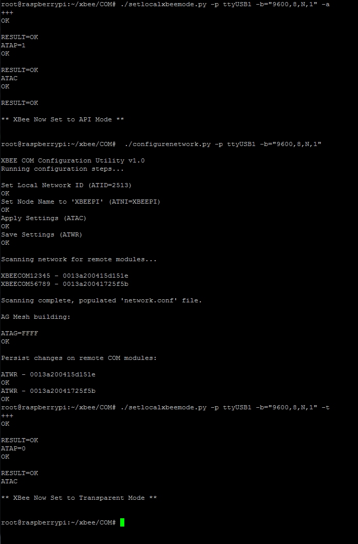
You can see from the above that the system has discovered 2 new end points :
XBEECOM56789
XBEECOM12345
Once this setup stage has completed we can then use the tool setlocalxbeedest.py to configure which remote RF-COM unit we wish the local unit to connect to.
Note that only one Local-Remote RF-COM connection can be created at a time, to gather data from the two end points we must change which remote RF-COM unit we are connected to between the two requests.
Making A Remote Request
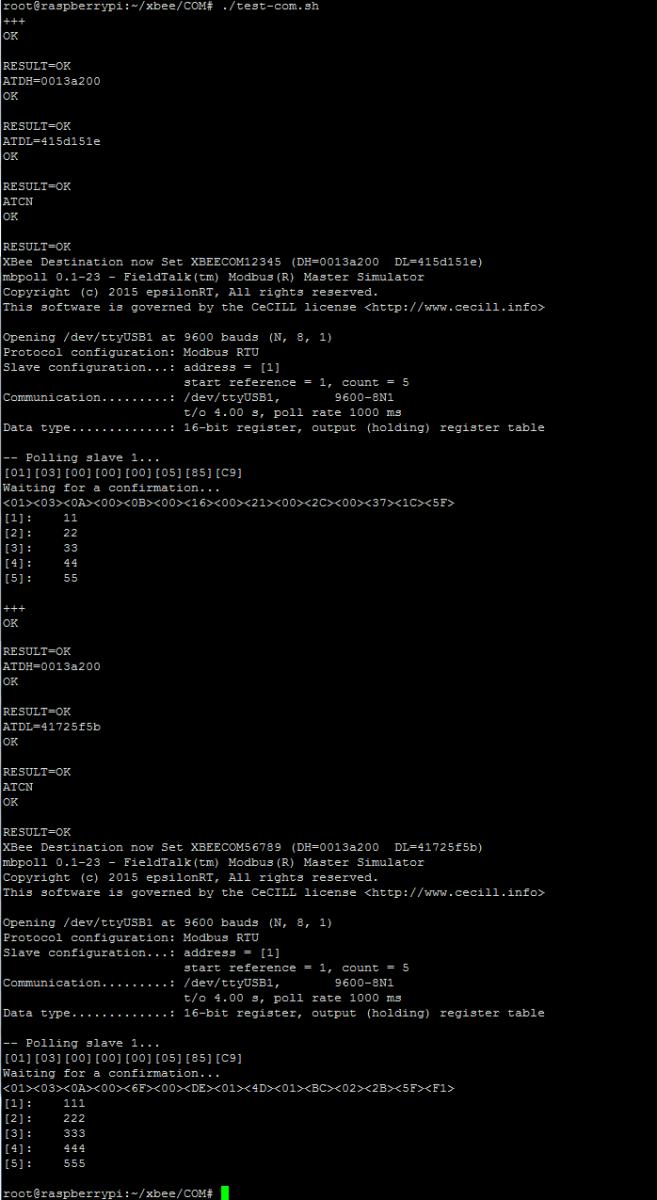
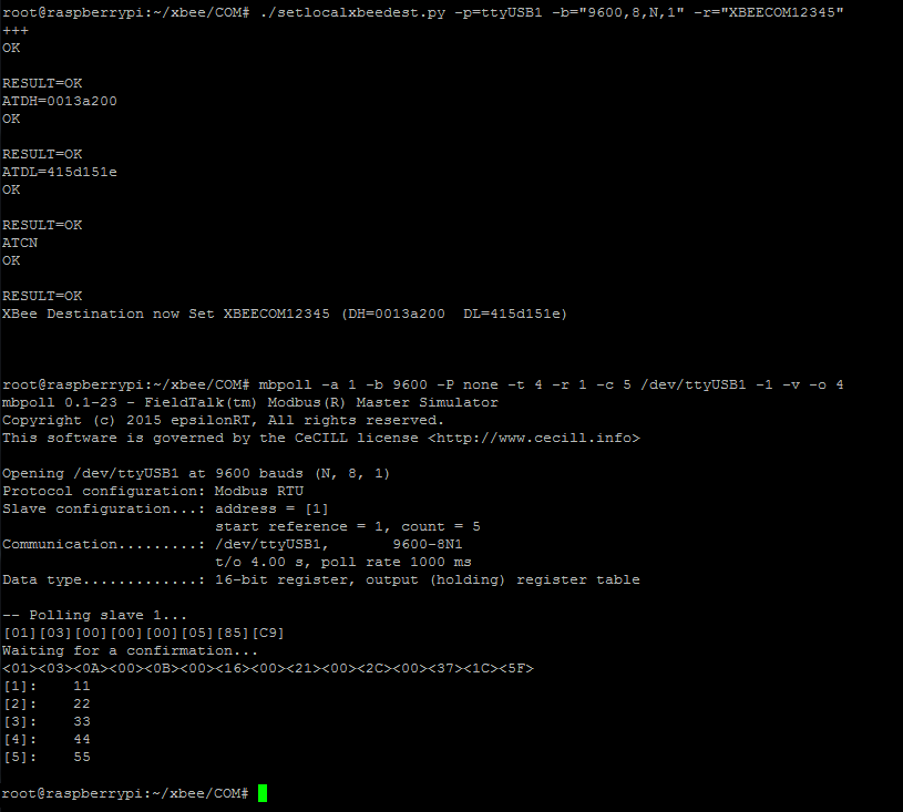
By running the below command pair we can connect the local RF COM unit to the remote unit named XBEECOM56789 and then run a Modbus request to obtain register values.
./setlocalxbeedest.py -p=ttyUSB1 -b="9600,8,N,1" -r="XBEECOM12345"
mbpoll -a 1 -b 9600 -P none -t 4 -r 1 -c 5 /dev/ttyUSB1 -1 -v -o 4
Likewise to obtain readings from both end points we need to change the target remote device in between.
./setlocalxbeedest.py -p=ttyUSB1 -b="9600,8,N,1" -r="XBEECOM12345"
mbpoll -a 1 -b 9600 -P none -t 4 -r 1 -c 5 /dev/ttyUSB1 -1 -v -o 4

./setlocalxbeedest.py -p=ttyUSB1 -b="9600,8,N,1" -r="XBEECOM56789"
mbpoll -a 1 -b 9600 -P none -t 4 -r 1 -c 5 /dev/ttyUSB1 -1 -v -o 4
This sequence can also be run inside a batch script to automate the process, here we have created a bash script called test-com.sh which has the above four lines in for illustration.