
Introduction
This app note aims to take the user through the installation and basic usage of the RTU-DI8 command tool line tool line tool for using Maxbotix Ultrasonic Sensors.
Download and install software
If not already installed, run the command below to install the libmodbus dependencies
# apt-get install libmodbus5 libmodbus-dev
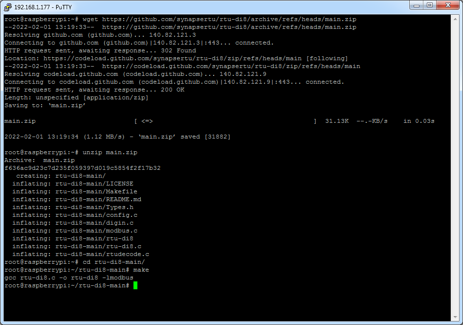
Next download and compile the demo app
$ wget https://github.com/synapsertu/rtu-di8/archive/refs/heads/main.zip
$ unzip main.zip
$ cd rtu-di8-main/
$ make
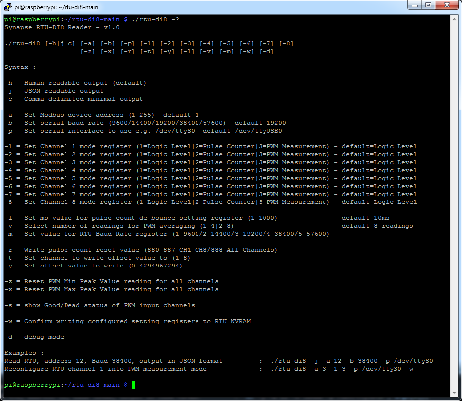
The tool provides a range of options to configure the unit
Check basic connectivity
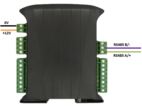
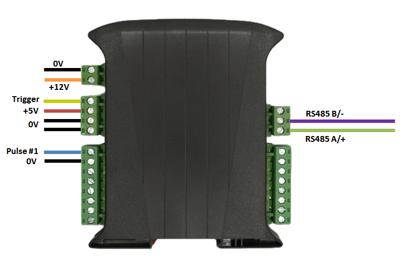
Connect up the unit as shown below, taking care to connect the RS485 signal wires to the correct ports
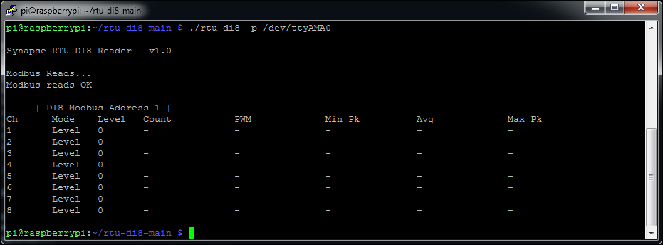
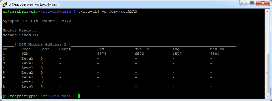
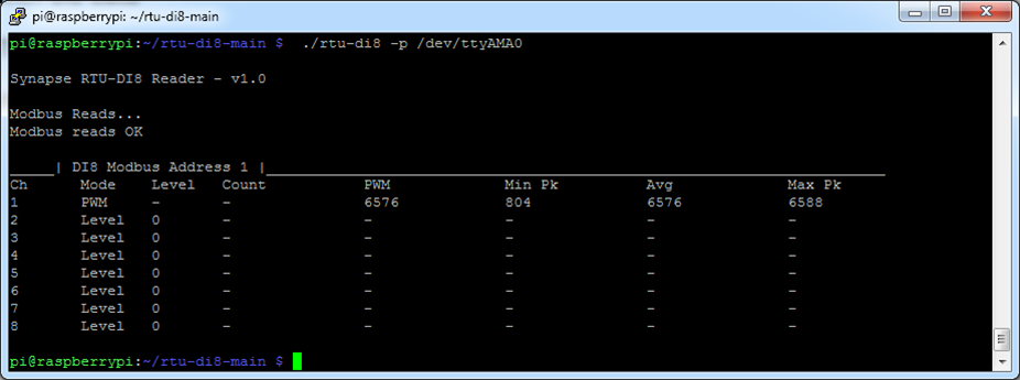
Run the tool to make a sample read, depending on which COM port you have the RTU device attached to you should alter the line below accordingly
$ ./rtu-di8 -p /dev/ttyAMA0
Configure Pulse Width Measurement Mode
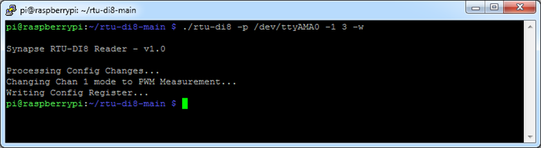
Next should switch channel 1 into PWM measurement mode for use with ultrasonic sensors
$ ./rtu-di8 -p /dev/ttyAMA0 -1 3 -w
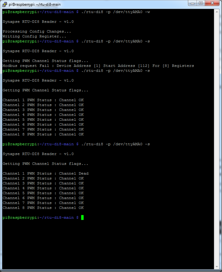
Due to the way the pulse measurement sub-system works the unit will not respond to Modbus requests whilst an active pulse measurement is occurring.
In order to prevent Modbus lock out if the RTU unit cannot locate a valid signal after 3 attempts it will mark the channel as dead and ignore it on subsequent cycles.
We can see the channel status by running the tool with the -s command line option.
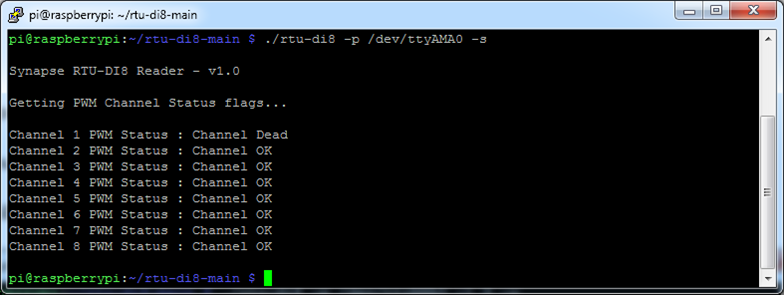
If you do not have a sensor plugged in, or the sensor has died/has a wiring issue, the RTU pulse width measurement subsystem will make three attempts to find a valid signal (once per channel cycle) and then mark the channel is dead and ignore it.
Each signal acquisition attempt will time out after approximately 2 seconds, during this process no modbus requests will be serviced.
To clear the channel dead status flag the user can either power cycle the unit or use -w command line option (write 255 to the config register) which will reboot the RTU unit
In this example we will use a Maxbotix LV-MaxSonar-EZ2 (MB1020) Sonar Range Finder to illustrate how to connect up one or more of this type of sensor.
The MB1020 has a scaling factor of 147µs=1 inch, with a 1 inch resolution limitation.
https://www.digikey.com/en/products/detail/maxbotix-inc/MB1020-000/7896789
This Maxbotix app note gives a background of how the Maxbotix ultrasonic sensors work
https://www.maxbotix.com/articles/how-ultrasonic-sensors-work.htm
Alternatives in the Maxbotix range can also be used, be sure to follow the respective application guide for any wiring differences or most suitable beam width/size.
We will be following the ‘Sequential’ setup described in the Maxbotix app note below
https://www.maxbotix.com/tutorials1/031-using-multiple-ultrasonic-sensors.htm
We will also be using the DIN rail mountable break out board for MaxBotix ultrasonic sensors :
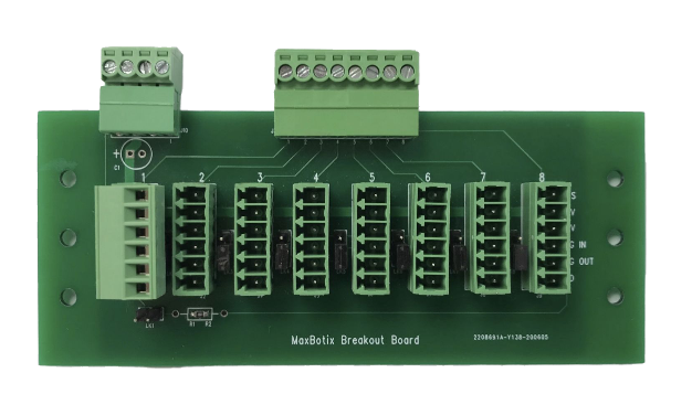
This breakout card aims to reduce to amount of complex wiring needed when using multiple sensors, and allows us to both feed power to the sensors as well as the trigger pulse to start the conversion sequence from the main RTU unit.
Sensor Wiring Schedule
The wiring schedule for connecting up the sensors is as shown below
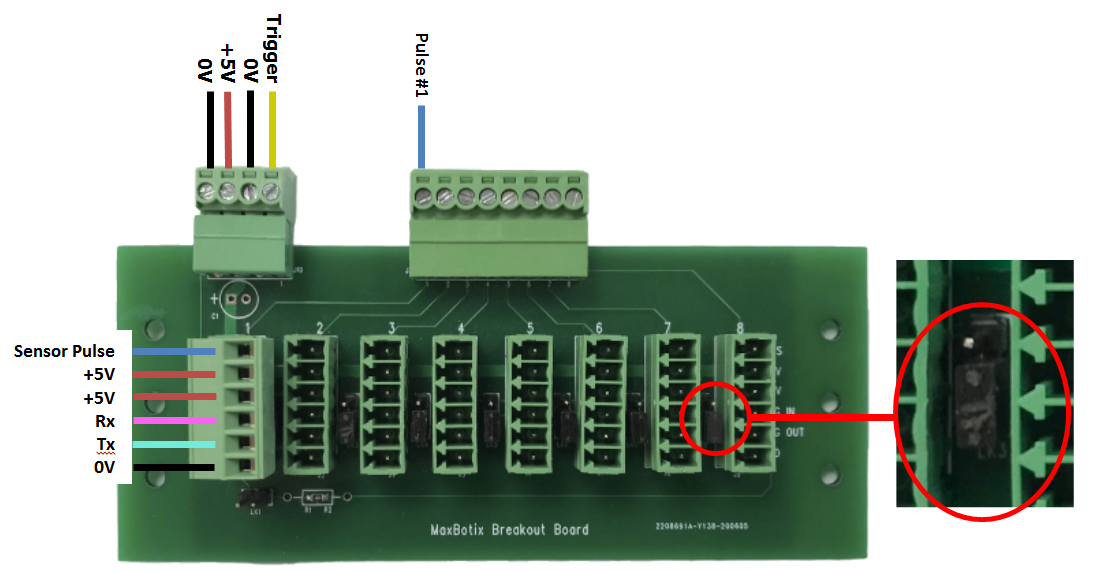
Note the position of the push on links to enable sequential triggering mode operation, all channels should be set as shown above
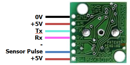
This setup chains the sensors together feeding the Tx line of the pulse sensor into the Rx of the following sensor channel, the Rx input of the first sensor is triggered from a 100µs Trigger pulse originating from the RTU unit when it initiates a PWM read cycle.
Checking this on an oscilloscope we could see that in this case, using the MB1020 sensor, the Tx lines from the each sensor are triggered at approximately +50mS intervals down the chain from the previous sensor trigger pulse.
Example Sensor Reads
Running the command line tool as shown below gives the attached sensor pulse width values in µS, the values can then be scaled in line with the sensor specification.
If we cover the sensor with our hand and remove it we can see the effect on the minimum peak levels
If we use the the -z option we can reset the minimum peak levels to the current readings
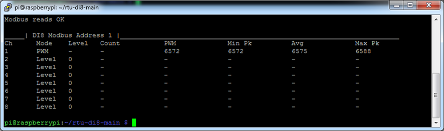
The same is also true for the maximum readings using the -x option
This ability to reset the counters provide a means to check what the max/min values seen in-between each Modbus poll.
Instead of resetting the max/min readings back to the live value, a specific 32bit value could also be written to the channel max/min register(s), which would then be used as the threshold to test the live readings against, and so could provide a means to set alarm levels.
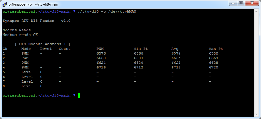
Up to 8 PWM sensors can be added to the unit in total, with a mix between level and PWM being possible as shown below, however It is not possible to mix pulse counting and PWM sensors on the same unit.
Cycle time
The max cycle time (i.e. the maximum rate at which all sensors can be read) is a function of the number of sensors multiplied by the refresh rate of one sensor. For the MB1020 this is approx. n * 50ms (for the XL-MaxSonar module this is n * 100ms)
In sequential mode each sensor provides the trigger signal to the next in the queue, which is why it is important to keep the sensors in order when connecting to both the breakout board and the RTU channel order.
i.e. if fitting 3 sensors use channels 1-3 and breakout board channels 1-3
To ensure the RTU unit does not overdrive the PWM sensor, possible if only 1 is attached or if the sensor has a slower reading rate, a configuration register has been included to allow the user to set the minimum PWM poll time.
Modbus register 124 sets this value, the default is 100ms (10Hz)
Sensor-to-Sensor Proximity
Using multiple ultrasonic sensors in an environment can cause crosstalk between the sensors. Generally, you want to make sure the sensors are as far away from each other as possible when mounting them in the final environment. Also, make sure the sensors are not pointed at each other and are as perpendicular to the intended target as possible.
Sensor Reading Stability
In our testing we have found for maximum stability it best to keep sensors (and the beams) as far apart from each other as is practical regardless of the triggering method.
Adding a 100uF capacitor to the breakout board resulted in increased long term reading stability when using multiple sensors.
Maxbotix provide a number of different types of sensor, varying in both granularity/resolution to beam shape, care should be taken to select and field test to find the most suitable one for the application.
Cabling
The use of good quality, low capacitance, low impedance shielded cabling is recommended. See app note below
https://www.maxbotix.com/Ultrasonic_Sensors/MB7954.htm
Data Averaging
The RTU unit uses the ‘Olympic average’ method of calculating averaging over either 6 or 10 readings (4 or 8 readings) depending on the setting.