Introduction
This app note aims to take the user through the installation and basic usage of the command tool line tool
The RTU-RTD unit can accept 2, 3 or 4-wire PT1000 temperature sensors, the default configuration is set for 2-wire sensors.
Download and install software
If not already installed, run the command below to install the libmodbus dependencies
# apt-get install libmodbus5 libmodbus-dev
Next download and compile the demo app
$ wget https://github.com/synapsertu/rtu-rtd4/archive/refs/heads/main.zip
$ unzip main.zip
$ cd rtu-rtd4-main/
$ make
.png)
The tool provides a number of different options for controlling and presenting datapoint values read from the RTU unit
.png)
Check Basic Connectivity
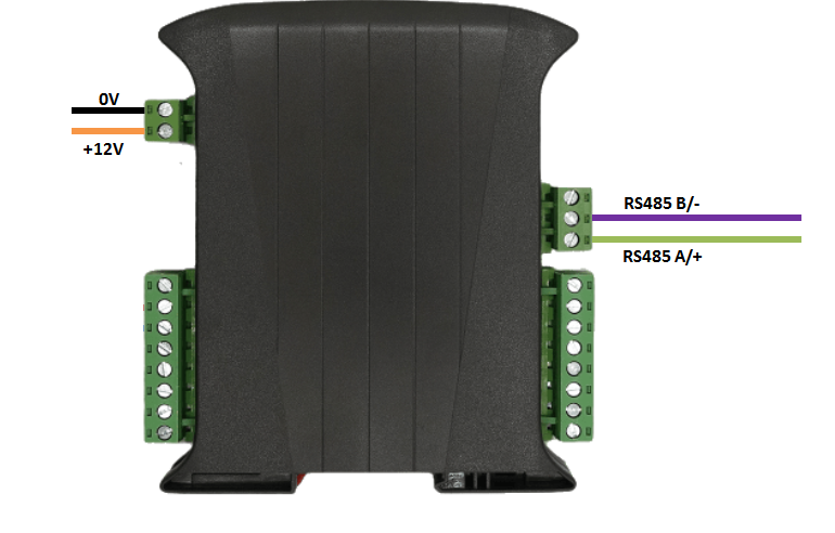
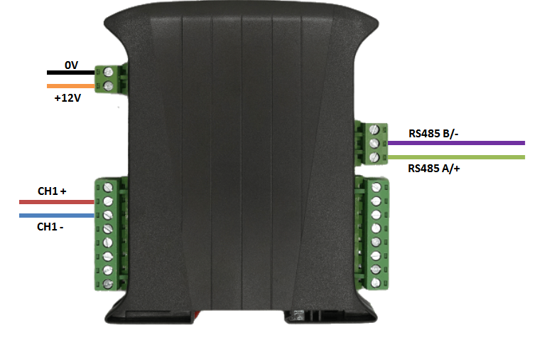
Connect up the unit as shown below, taking care to connect the RS485 signal wires to the correct ports
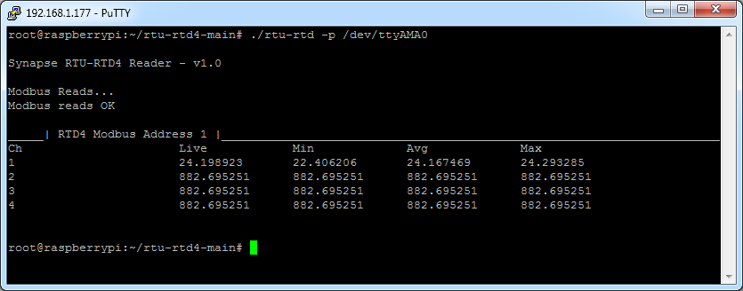
Run the tool to make a sample read, depending on which COM port you have the RTU device attached to you should alter the line below accordingly
$ ./rtu-rtd -p /dev/ttyAMA0
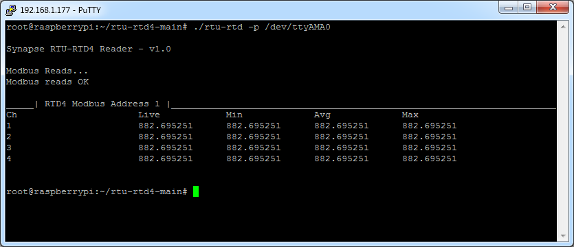
If you do not get a response check your RS485 cabling and connection order
A reading of 882 is the open circuit value, if this value is seen on a live system then this is indicative of a damaged sensor.
Sensor Wiring
For this example we will use a pre-wired PT1000 sensor : https://uk.rs-online.com/web/p/rtd-sensors/8968399
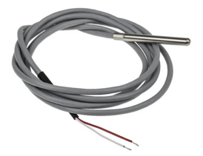
The sensor should be connected up as shown below
Note : Plug the sensor in before powering up the unit
Run the below to make a sample read
$ ./rtu-rtd -p /dev/ttyAMA0

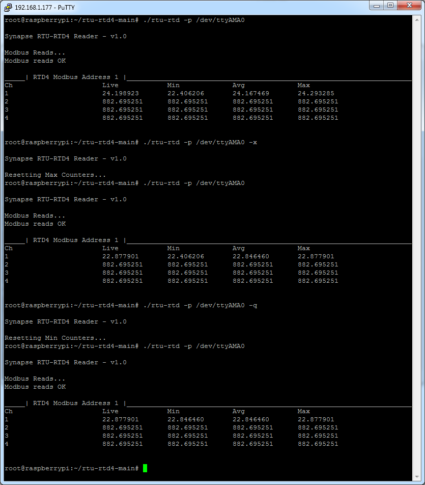
By holding the sensor in your hand you can alter the read temperature
The Max/Min counters can be reset using the -q and -x command line parameters
This provides the ability to capture the peek values seen by the unit inbetween Modbus polls