Introduction
This app note aims to take the user through the installation and basic usage of the command tool line tool
The RTU Digital Ouput unit provides 8 x N.O. Relay contacts that the user can employ to activate AC or DC appliances up to 5A (resistive load) - Take note of the relay specification for dealing with inductive loads
Equally the on board relay could be used to drive a larger external relay.
Download & Install Software
If not already installed, run the command below to install the libmodbus dependencies
# apt-get install libmodbus5 libmodbus-dev
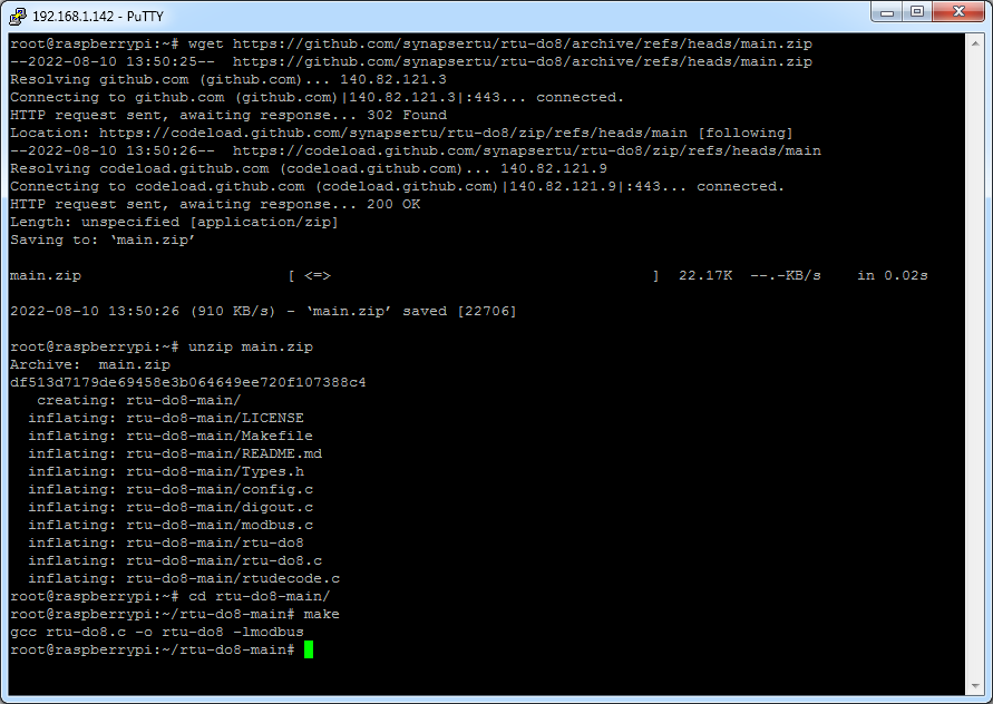
Next download and compile the demo app
$ wget https://github.com/synapsertu/rtu-do8/archive/refs/heads/main.zip
$ unzip main.zip
$ cd rtu-do8-main/
$ make
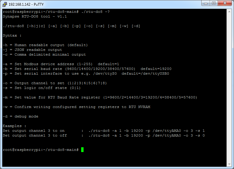
The tool provides a range of options to configure the unit
Check Basic Connectivity
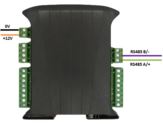
Connect up the unit as shown below, taking care to connect the RS485 signal wires to the correct ports
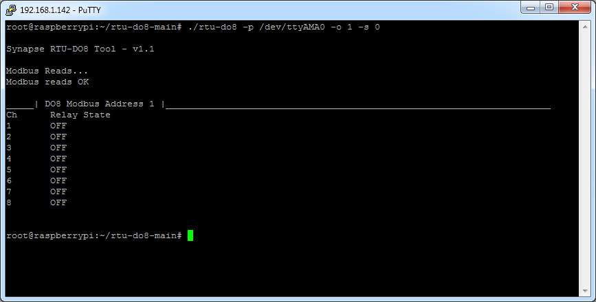
Run the tool to make a sample read, depending on which COM port you have the RTU device attached to you should alter the line below accordingly
$ ./rtu-do8 -p /dev/ttyAMA0

If you do not get a response check your RS485 cabling and connection order
LED Example
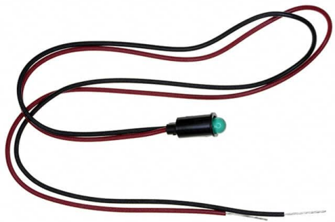
In this example we will show how to connect up the unit to control an external dummy load by using an LED with built in resistor. Dialight 559-0203-027F / 559-0203-007F will work fine for this appliaction.
https://www.digikey.com/en/products/detail/dialight/5590203007F/1693261
The RTU module should then be connected up as shown below
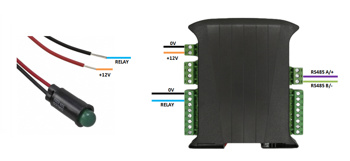
Run the the command below and the relay will switch on and the LED will light up
$ ./rtu-do8 -p /dev/ttyAMA0 -o 1 -s 1

Run the the command below and the relay will switch off and the LED will go off.
$ ./rtu-do8 -p /dev/ttyAMA0 -o 1 -s 0