Introduction
This app note aims to take the user through the installation and basic usage of the command tool line tool
The RTU Digital Input unit can operate in three modes:
- Voltage Level sense
- Pulse counter**
- PWM measurement**
** These modes are mutually exclusive, so you cannot operate the unit with channels configured in both modes
Download & Install Software
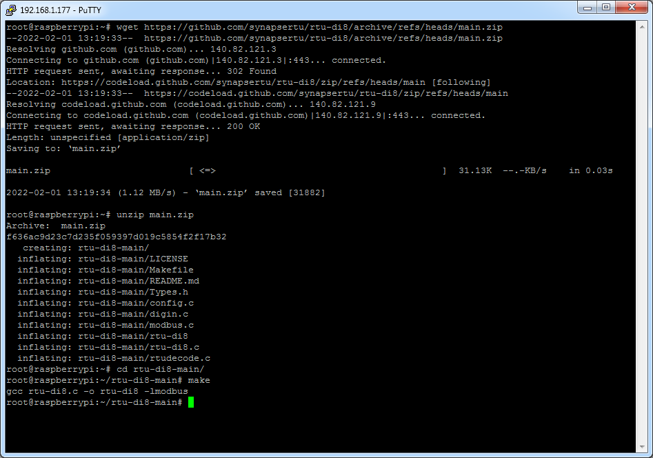
If not already installed, run the command below to install the libmodbus dependencies
# apt-get install libmodbus5 libmodbus-dev
Next download and compile the demo app
$ wget https://github.com/synapsertu/rtu-di8/archive/refs/heads/main.zip
$ unzip main.zip
$ cd rtu-di8-main/
$ make
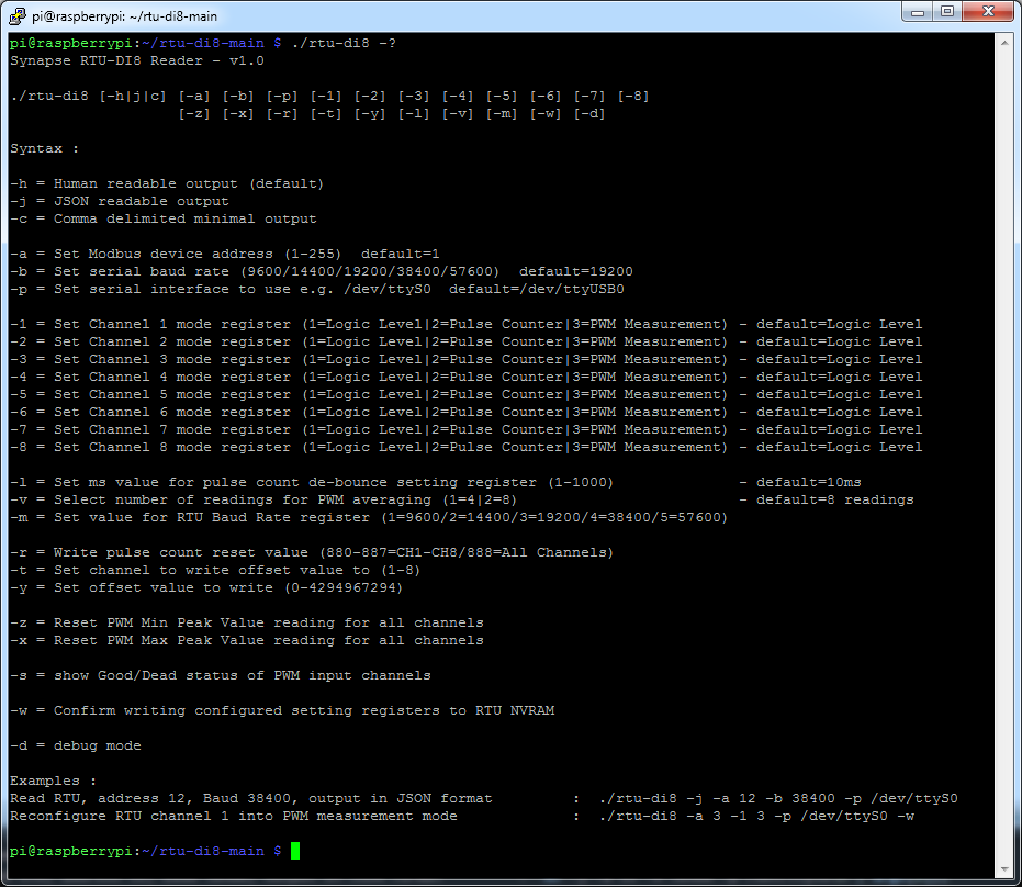
The tool provides a range of options to configure the unit
Check Basic Connectivity
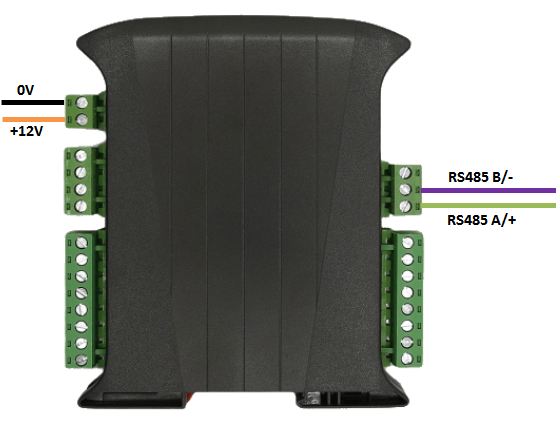
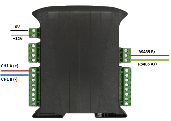
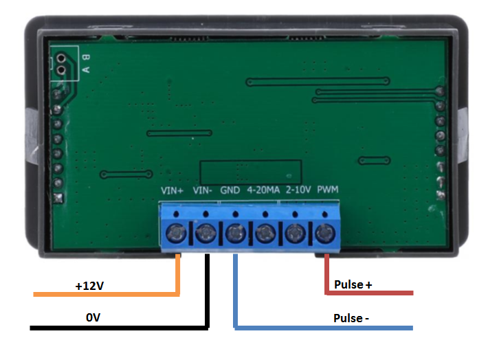
Connect up the unit as shown below, taking care to connect the RS485 signal wires to the correct ports
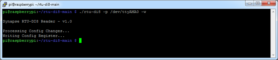
Run the tool to make a sample read, depending on which COM port you have the RTU device attached to you should alter the line below accordingly
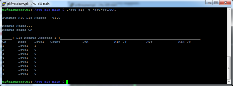
$ ./rtu-di8 -p /dev/ttyAMA0
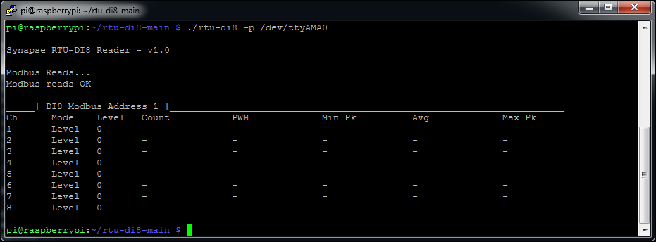
If you do not get a response check your RS485 cabling and connection order
Mode 1 – Level
In this example we will show how to connect up the unit to test level inputs, here we can use any positive DC voltage of >=5V
The digital input inside the unit is configured as follows
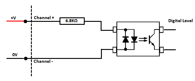
By attaching the the RTU's Power Supply Unit's 0V to Channel 1 negative and then connecting/disconnecting the Power Supply Units positive power lead to Channel 1 postiive we can see a level state change on channel 1
Signal Generator Box
This simple multifunction tool provides the developer with a way to simulate plant equipment inputs without the need for expensive and bulky equipment.
The device can output a number of functions; in this case we will concentrate on Pulse output
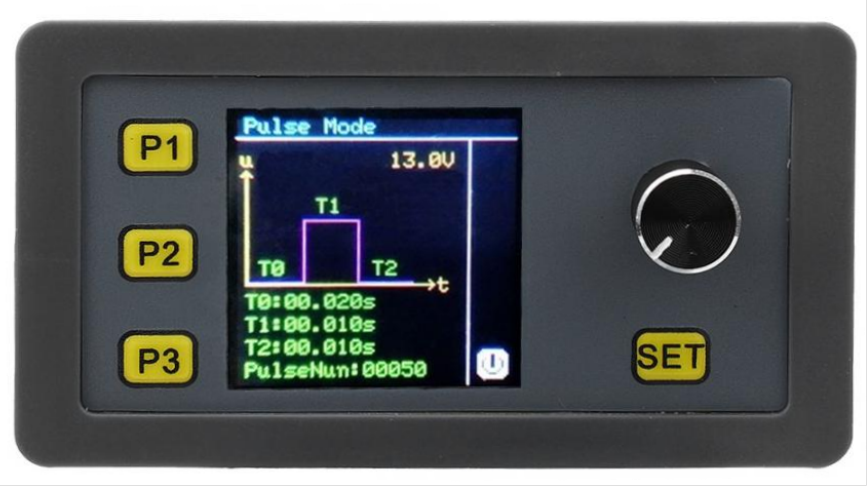
| Button | Function |
| P1 | PWM mode |
| P2 | Pulse Mode |
| P3 | Signal Source Mode |
| SET | Cycle through output settings |
| Dial |
(Set Mode) Rotary action controls value (Set Mode) Button click controls switching between decimal side (Active Mode) Button click starts pulse/analogue signal sequence |
Mode 2 – Pulse Count Mode
First wire up the system so the signal generator box to the RTU unit as shown below;
Next we need to reconfigure channel 1 into pulse count mode
$ ./rtu-di8 -1 2 -p /dev/ttyAMA0 -w
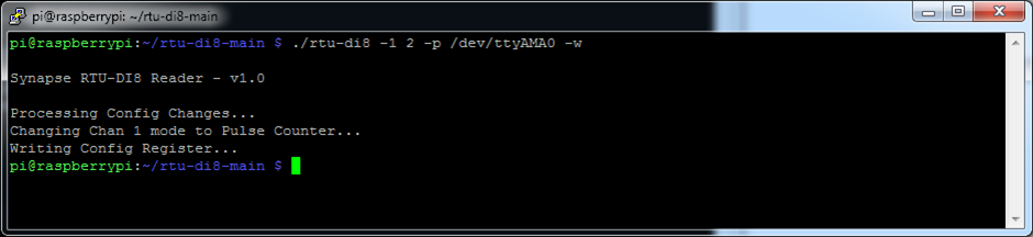
RTU Channel 1 unit has now been set to Pulse Count mode
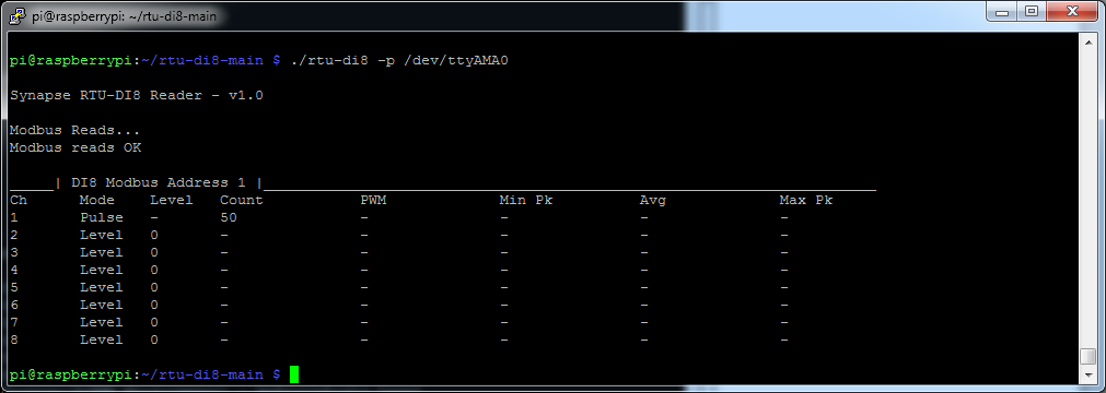
$ ./rtu-di8 -p /dev/ttyAMA0
On the signal generator unit click button P2 to enter Pulse mode, the press SET repeatedly to alter the three T parameters,
Note that T0+T1 must be greater than the device debounce setting, which is factory set to 10ms (0.010s), for the pulse to be recognised.
Pressing the dial button will switch between left and right of the decimal point, turning the dial will adjust the value up and down
Configure the pulse settings on the signal generator to those in the below table
| Setting | Value |
| T0 | 0.020s |
| T1 | 0.010s |
| T2 | 0.010s |
| Pulse Num | 50 |
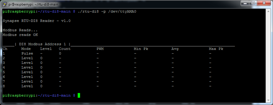
Next exit set mode (so no settings are in red) by and click the rotary dial to start the pulse sequence, once the sequence has completed run the below to get an updated reading
$ ./rtu-di8 -p /dev/ttyAMA0
If you power the RTU unit off and back on again at this point you will notice that the count has been retained. Each time a pulse is detected the updated pulse count total is re-written immediately to internal non-volatile FRAM memory.
Note that due to a quirk in the way the signal generator operates powering off/on both the signal generator and the RTU unit will cause an extra pulse to be counted as the signal generator initialises.
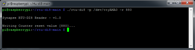
We can reset this counter value by using the –r command line switch and using the value 880 to reset channel 1 counter
Values between 880 and 887 target single counters between for Channels 1 to 8 respectively, a value of 888 will reset all counters.
Note this action is applied immediately
$ ./rtu-di8 -p /dev/ttyAMA0 -r 880
A positive offset value can be internally applied to the count value for each channel, this can also be set using the tool and the -t and -y command line options
$ ./rtu-di8 -p /dev/ttyAMA0 -t 1 -y 1000
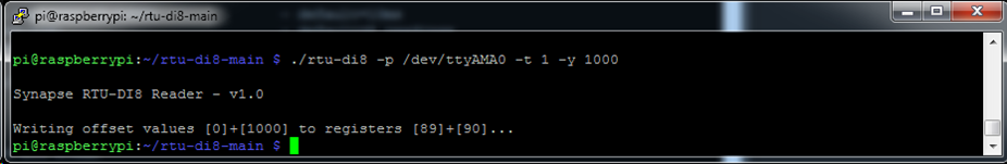
The offset is immediately applied but it is not immediately saved (so lost if the unit is powered off/on) until 255 is written to the config register.
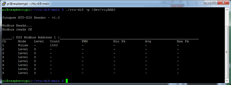
We can save this value to the internal EEPROM to make the setting persistent
$ ./rtu-di8 -p /dev/ttyAMA0 -w
A power cycle at this point will not affect the reading as the offsets have now been saved/read back from EEPROM