
Introduction
This app note aims to take the user through the installation and basic usage of the command tool line tool
The RTU Analogue Input unit can operate in three modes:
- 4-20mA Current Loop Measurement
- 0-10V Voltage Input Mode
- 0-2V Voltage Input Mode
IMPORTANT : Note power off both sensor(s) and RTU unit before attaching/removing any wiring
Download and install software
If not already installed, run the command below to install the libmodbus dependencies
# apt-get install libmodbus5 libmodbus-dev
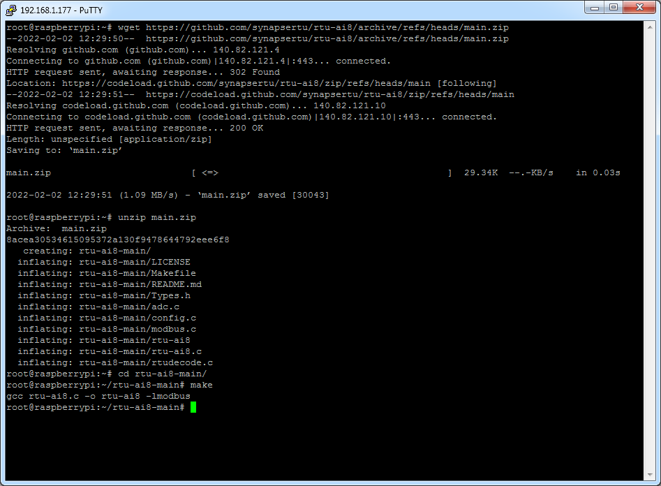
Next download and compile the demo app
$ wget https://github.com/synapsertu/rtu-ai8/archive/refs/heads/main.zip
$ unzip main.zip
$ cd rtu-ai8-main/
$ make
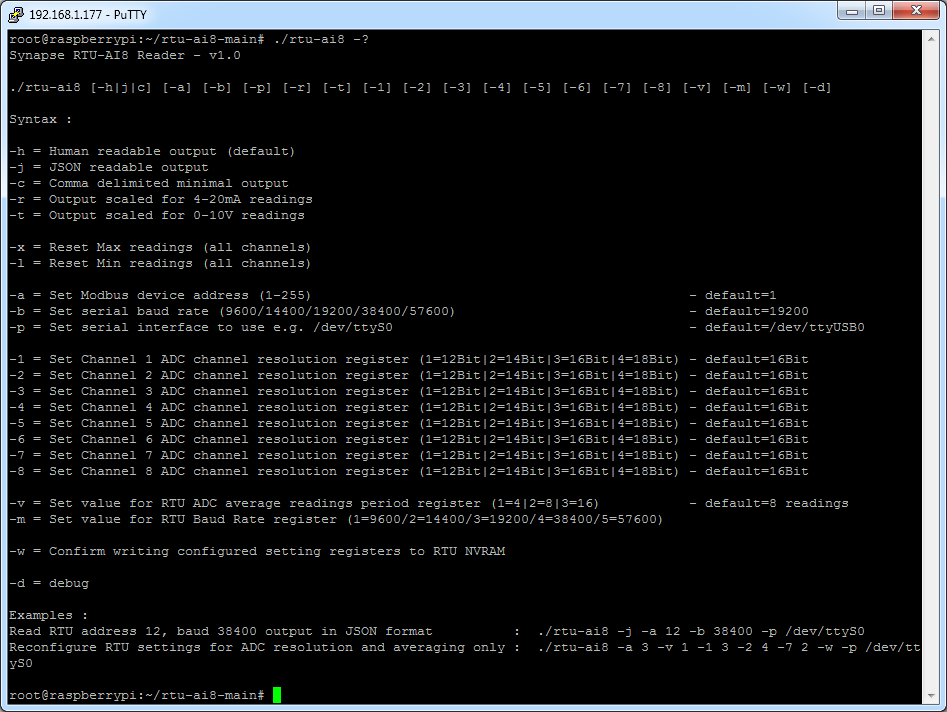
The tool provides a number of different options for controlling and presenting datapoint values read from the RTU unit
Check Basic Connectivity
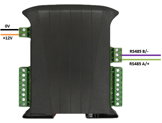
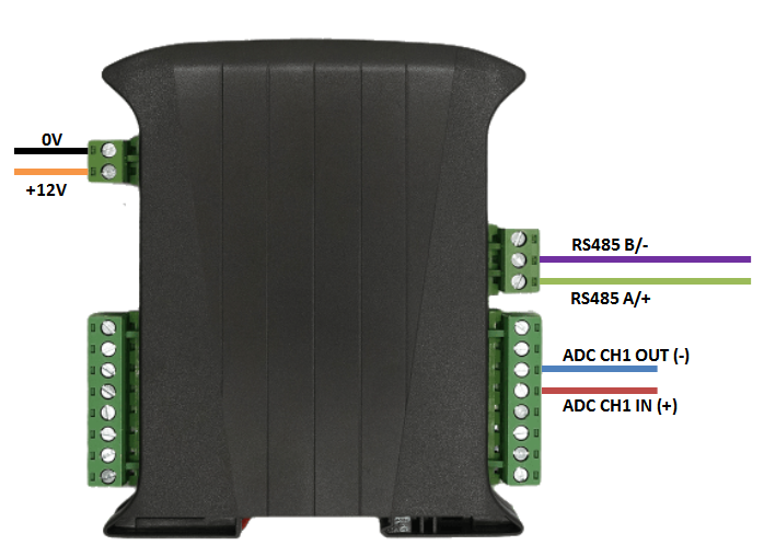
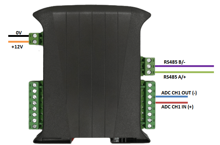
Connect up the unit as shown below, taking care to connect the RS485 signal wires to the correct ports
Run the tool to make a sample read, depending on which COM port you have the RTU device attached to you should alter the line below accordingly
$ ./rtu-ai8 -p /dev/ttyAMA0
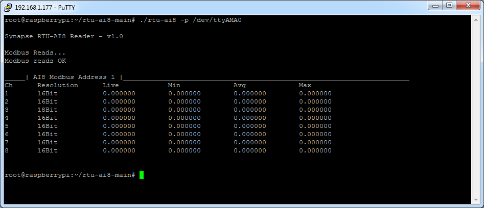
If you do not get a response check your RS485 cabling and connection order
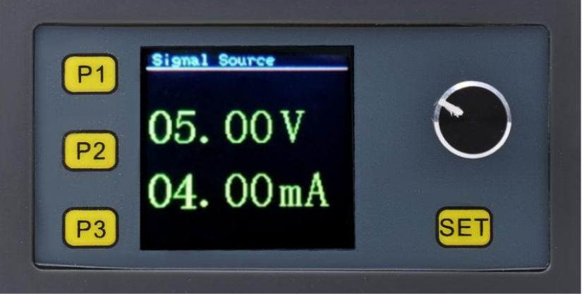
Signal Generator Box
This multifunction tool provides the developer with a way to simulate plant equipment inputs without the need for expensive and bulky equipment.
The device can output a number of functions, in this case we will concentrate on the 4-20 and 0-10V output
We have calibrated this using our own current loop and DVM tools however the expected accuracy based on what we have observed is limited to around +/- 0.2% over the scale in either mode.
| Button | Function |
| P1 | PWM mode |
| P2 | Pulse Mode |
| P3 | Signal Source Mode |
| SET | Cycle through output settings |
| Dial |
(Set Mode) Rotary action controls value (Set Mode) Button click controls switching between decimal side (Active Mode) Button click starts pulse/analogue signal sequence |
Click button P3 to enter signal source mode, the press SET repeatedly to alter either the voltage or the current output setting.
Pressing/Clicking the Dial Button will switch between left and right of the decimal point, turning the dial will adjust the value up and down
The unit can be recalibrated by pressing and holding the dial button for 5 seconds whilst powering the unit up, note that this should be done with care and using a suitable loop calibration tool like a DRUK UPS-II unit.
4-20mA Mode
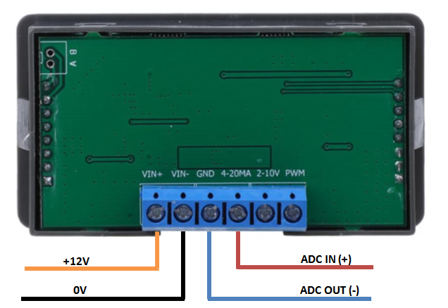
Wire up the signal generator and RTU unit as shown below for 4-20mA operation
Internal RTU Channel Mode Link Settings (Default - No change from shipped setting needed)

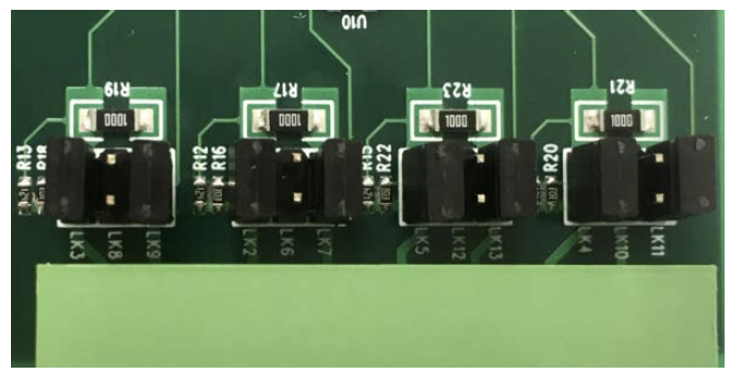
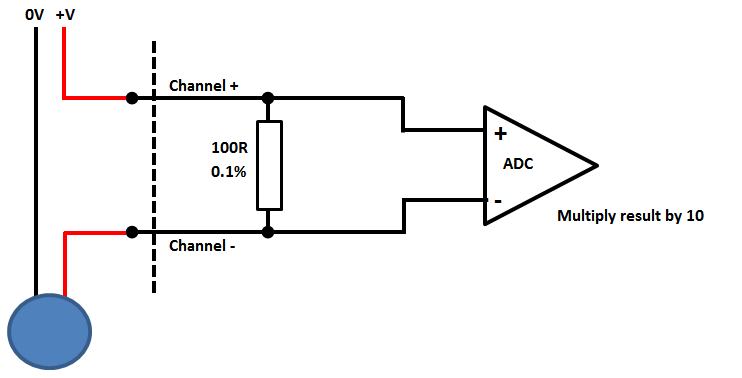
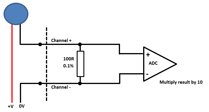
The RTU unit uses a precision 0.1% 100R resistor to convert 0-20mA to 0-2V
Current loop sensors can be attached in either "High Side" or "Low Side" configuration, in our example we use "high side" configuration
Where in doubt as to the scheme to use connect sensors as low side configuration.
High Side 4-20mA configuration
Low side 4-20mA configuration
Make a sample read request to the unit with the -r command line option to scale the value
$ ./rtu-ai8 -p /dev/ttyAMA0 -r
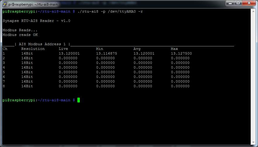
If we alter the value on the dial (reducing the setting) and re-run the tool we can see the peek reading has been captured and the minimum has been altered in sympathy with the new reading

To reset the max/min readings, which will then use the current value as the threshold, use the -x or-l command line option.
This ability to reset the max/min counters provide a means to check what the max/min values seen in-between each Modbus poll.
More advanced users can alter the tool to allow a specific (raw ADC) value to be programmed to the min/max value, and which will then be used to test against and can form the basis of an alarm function.
0-10VDC Mode
Connect up the Signal Generator Box and the RTU unit as shown below
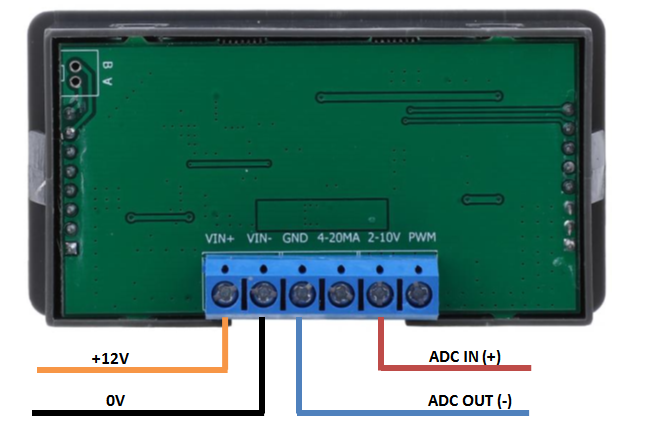
Internal RTU Channel Mode Link Settings to voltage input mode

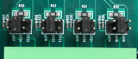
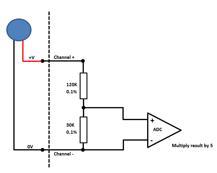
In this mode the RTU unit uses a precision 0.1% voltage divider to scale down the voltage 5:1 allowing the internal ADC range of 0-2V to read 0-10V
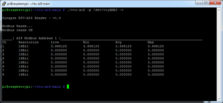
Make a sample read request to the unit with the -t command line option to scale the value for 0-10V
$ ./rtu-ai8 -p /dev/ttyAMA0 -t
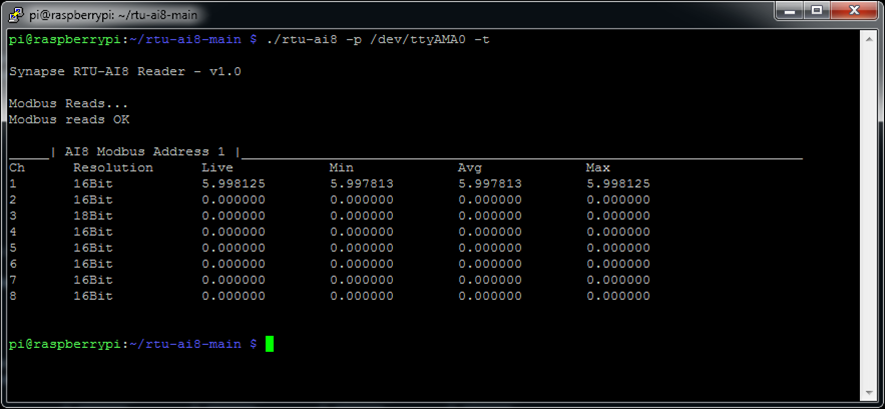
Altering the value on the signal generator box down results in a lower reading recorded, whilst keeping track of the peek value seen
To reset the max/min readings, which will then use the current value as the threshold, use the -x or-l command line option.
This ability to reset the max/min counters provide a means to check what the max/min values seen in-between each Modbus poll.
More advanced users can alter the tool to allow a specific (raw ADC) value to be programmed to the min/max value, and which will then be used to test against and can form the basis of an alarm function.